THE SCORPION 4 ALPHANUMERIC BASIC USER GUIDE:
-------------------------------------------------------------------------------------------------------------------------------------------------------------------------------------------------------------
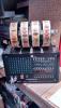
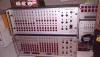
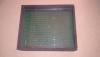
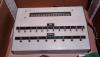
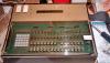
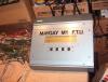
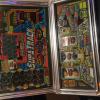
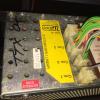
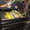
This is a very basic guide to making use of one of these displays. It applies to the chunkier version in scorpion 4 - has two capacitors and a massive resistor on the back , its issue number -
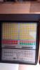
31-821-001 issue 1 (did I get that right????) And the more recent matrix display found in the later scorpion 5 games. Its not an official manual, fuck I dont even think they have a manual they probably did the same as me when they ordered the on board ASICs from NEC, who knows. But it works for me , as you can see, and it should work for you. If you ever want to tinker with one of these that is. Which you probably wont, but I need something to do.
Not exactly a pro intro to a manual is it? lol thats what happens when you start dreaming things up when on a caffiene rush from rockstar haha!!
Anways I hope you make use of it. I probably will at somepoint make a proper one and PDF it all up , along with the various other things that will appear out of me in the next few months. If its all bullshit I apologise in advance!!
1) the pinout -
The display has a 6 pin connector :
1- +12v
2 -clock
4-data
5-reset
6- Ground
So it can be powered from a +12vdc adaptor, or a PC power supply easily . BFM machines due to a design flaw actually hit it with +13.5v so its got a wee bit of tolerance in it.
2a) Resetting :
To reset the display you need to supply it with a +5v logic level for a minimum of 30ms. I actually think you should hold it for a second or so because sometimes you can reset the display and its still in the mode it was before.
2b) Clock speeds:
I am afraid you will need to experiment as every computer is different ! I am pulsing the clock on the display at about 30-40ms.
3) Connecting the display to the computer :
You will need an older motherboard, or a laptop with a parralel port . If you are using a laptop be aware that the levels output by it are sometimes lower than 5v which can cause the display to misbehave, in that case you will need to hook it up via a 74ls244 buffer . Theres a bit about that later.
On a PC motherboard tho its simply a case of connecting data, clock and reset to pins 3,2 and 8 of the parralel connector. If you want to try out the driver written for it that is.
Once you have your display hooked up you will also need to download inpout32.dll from logik4u.net as it needs this library to allow the port to run in windows XP which normally does not support direct port addressing.
4) Using the display :
4a) Character and command codes.
The display accepts an 8 bit serial transmission with no start or stop bits. I was not sure how to configure a com port which is why I chose to use the parralel port. The bits are arranged as follows :
bit7 - control bit
bit6 - unused in character mode, bit6 in command mode
bit5 - character bit 5
bit4- character bit 4
bit3- character bit 3
bit2- character bit 2
bit1- character bit 1
bit0- character bit 0
Bit 7 determines weather you are sending it a command or character code. Note that when you are sending a character and not a command it ignores bit 6, but you still have to send it otherwise your data stream is not in sync. To send the bits out you place the relevant bit value on pin 2 of the port and then provide it a LO clock pulse . That is a HI-LO. I actually tried it both ways round pulsing it low seems to work best. If you use a logic probe to check the clock and data pins on the display with no activity from the computer they are being pulled hi by resistors on the display.
If Bit7 is 0, then you are sending a character, if it is 1 , then you are sending it a command. In command mode bit6 becomes part of the 8 bit command code.
4b) Sending the data :-
Obviously you can't just put the data value on the port . We have to break it up into its revelant bits first. Its easy enough tho with some bitwise maths. You simply AND your value with the individual binary values for each bit. For example to find the correct value for bit 4 you AND your data value with 16. If bit 4 of your number is 1 your result will be 16. If its 0 your result will be 0. The software provided does this for all 8 bits of a given number and any values that are not 0 it converts them to logic 1.
Once the value to be transmitted to the display is broken up into its relevant bits it is then sent out to the display , bit 0 first, bit 7 last. It is important to get that the right way round, because if you do it the wrong way round , ie bit 7 FIRST, like I did for hours, then you are sending command codes not characters and it can result in lets say, some funny or downright annoying behaviour in the display . Normally you will put it into an unknown state, and unless you know how to get it back out of it you will have to reset it to get back to buisness.
So remember , break the value up into its bits by ANDing with 1,2,4,8,16,32,64,128 , and then clock it over sending it in the order of least significant bit first , most significant last (or for the layman, bit 1 first and bit 7 last.)
4c) Sending character codes :
It couldnt be simplier, it accepts standard ascii codes for all the letters, numbers and symbols. it has 64 characters in its memory. Seems to be upper case only but that doesnt matter- your letters, numbers , and grammatic and mathematic symbols are all there and easy to use. Sending it a value from 0- 64 will cause the right character to appear on the display. For example sending it ascii value 2 will cause the letter B to appear. Now if you refer to datasheets etc online you will notice that the ascii codes for uppercase letters and symbols are actually in the range from 64-127, not 0-64 , but this doesn't matter to the display as it is ignoring bit 6 in character mode so it is still accepting values from 0-64.
4d) Special characters and slight differences:
The display has a couple of built in special characters. Ascii code 36 is a dollar sign for example. But send code 37 instead , and the character previously displayed will flash. Note the display has to be set up to do this, more later. Also the asii code for a £ sign causes a direction change in the displays printing. So to show £ on the display , send it the code for ! instead.
5) Sending command codes:
The display has quite a range of instructions you can send it. I am sure I havent found them all, and there are one or two I have found that I still have not fully figured out, but here are the ones I think you can use. As you set the display to command mode by setting bit7 to 1 the command codes appear as ascii codes 128-255. Note some command codes will then require one or more values to be sent after them to work , it is advisable to use the display blanking command to switch it off while you carry out these commands.
COMMAND CODE - OPERATION -
128 Display blanking - simply switches the display glass off. Doesnt clear the memory characters will be restored when blanking is turned off.
129 Display blanking off .
130 and 131 Same as previous two codes, except action is performed on "window areas" if you have set a window up at some point
132 + 1 value Set brightness level. Brightness value can be 1- 6. 1 being brightest , and 6 darkest. Value has to be sent as an ascii code, so to set
Brightness 1 , you send it command code 132, and then character code 1.
133 Enable user defined character mode (also turns flash mode off)
144-151 Set start address (send a number from 144-151 to select which of the 16 digits to start showing characters from
160 Display prints to right (You characters are printed from left - right and will wrap around back to left if you print more than 16 characters)
161 Display prints to left (wraps around to right)
162 Display scrolls to right
163 Display scrolls to left (can cause decimal point, full stop or commas to be displayed in wrong place, ie before letter instead of after it.)
168 + 7 values Reprogram character to user defined graphic. A bit tricky to use I will put a seperate section up for it. Also the 7 numbers after the
Command code are not ascii values but are true 8 bit numbers.
172 Multiplexer test - the display goes through a test pattern to ensure the glass and driving row and coloumn multiplexers are working.
177 CLS /Clear screen . Does exactly what it says on the tin. Doesnt reset the character address tho so if your last character was shown
At position 7 when you start printing fresh characters you will still be at position 8
184 +1 value Unknown - Tried it every which way doesn't seem to have an effect on characters or display.
188 Reset character set - Gets rid of any user definitions you made to the character set.
200 Flash mode on. Only works if command 133 has not been sent. Use this code to allow the flash character (ascii 37) to work.
220 +2 values Unknown- Sometimes causes display reset so mabye something to do with factory testing
225 -241 Inhibit clear screen for specified area . You can select how many digits do not get cleared by code 177. 227 stops you clearing the
first 3 locations on the display glass.
245-249 Control of window areas, I havent experimented with them yet.
254/255 Reset window areas.
Note there are a couple in the set I specify as unknown. They do SOMETHING, but atm I am not sure what. I will in time figure out what they are for.
Also note that some commands cause others not to work. You have to reset the display to reverse the effects of this.
Section on user defined characters to follow.
Edited by MAGIK, Yesterday, 11:57 pm.
Thats why they call me magik!